GPIO Driver
The GPIO Driver manages the General Purpose IOs on a gateway using the Driver model. Based on the GPIO Service, the driver can be used in the Wires framework, the Asset model or directly using the Driver itself.
Features
The GPIO Driver includes the following features:
- support for digital input and output
- support for unsolicited inputs
- the trigger event can be configured directly through the Driver
Installation
As the other Drivers supported by Eclipse Kura, it is distributed as a deployment package on the Eclipse Marketplace for Kura 3.x and 4.x/5.x. It can be installed following the instructions provided here.
Instance creation
A new GPIO Driver instance can be created either by clicking the New Driver button in the dedicated Drivers and Assets Web UI section or by clicking on the + button under Services. In both cases, the org.eclipse.kura.driver.gpio factory must be selected and a unique name must be provided for the new instance.
Once instantiated, the GPIO Driver is ready to use and no configuration is needed.
Channel configuration
The GPIO Driver channel can be configured with the following parameters:
- enabled: it allows to enable/disable the channel. If it isn't selected the channel will be ignored.
- name: the channel name.
- type: the channel type, (
READ,WRITE, orREAD_WRITE). - value.type: the Java type of the channel value. The value read by the Driver will be converted to the value.type. Conversely, in write operations the Driver will accept value of this kind.
- listen: when selected, a listener will be attached to this channel. Any event on the channel will be reported using a callback and the value will be emitted.
- resource.name: the name of the GPIO resource as reported by the GPIO Service. The
#select resourceselection has no effect on the channel. - resource.direction: the direction of the GPIO. Possible values are
INPUTandOUTPUT. The#select directionselection has no effect on the channel. -
resource.trigger: the type of event that triggers the listener, if selected. Possible values are:
-
NONE: no event will trigger the listener. RISING_EDGE,FALLING_EDGE,BOTH_EDGES: the listeners will be triggered respectively by a low-high transition, a high-low transition or both.HIGH_LEVEL,LOW_LEVEL,BOTH_LEVELS: the listeners will be triggered respectively by the detection of a high, low or both levels. Please note that these options aren't supported by all the devices.
Drive a LED using the GPIO Driver
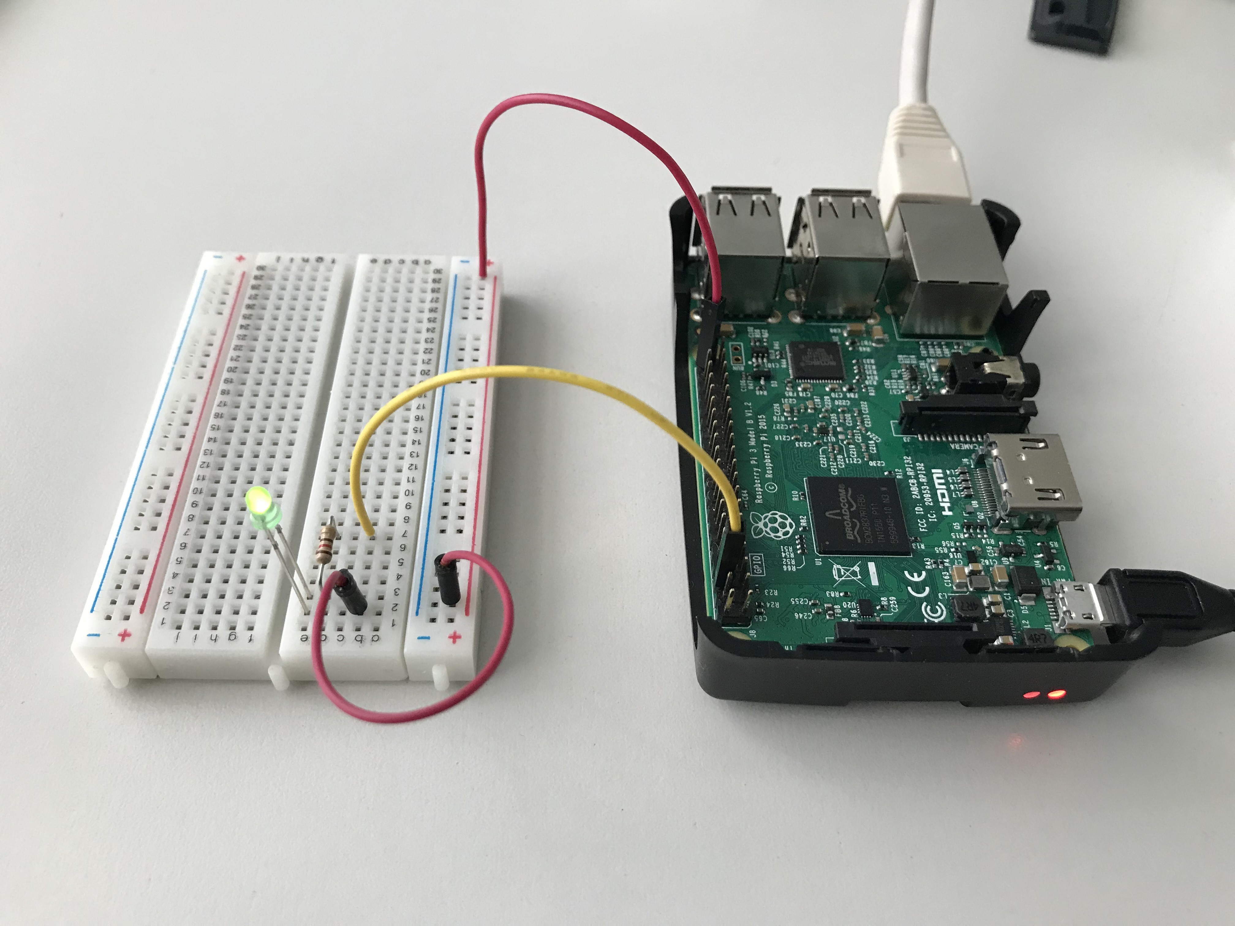
In this section a simple example on the GPIO Driver using a RaspberryPi will be presented. Before configuring the Driver, arrange a setup as shown in the following picture, using a breadboard, a led, a 120-ohm resistor and some wires. Connect the yellow wire to a ground pin on the RasperryPi connector (i.e. pin 6) and the red one to pin 40 (a.k.a. gpio21).
From the Drivers and Assets tab, create a new GPIO Driver, call it GPIODriver and add an Asset as shown in the following picture.
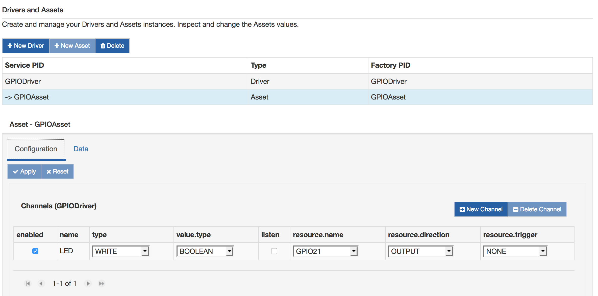
The asset is configured to manage a gpio, called LED, as an output and drives it writing a boolean value. The LED channel is attached to the gpio21 on the RaspberryPi. In the Data tab, fill the Value form with true and press Apply: the green led will switch on. Writing a false will switch off the led.