GPIO Driver Application
In this section a simple but effective example of the GPIO Driver on Wires will be presented. This example will implement a Wire graph that toggles a digital GPIO. A listener will be attached to an input GPIO externally connected to the first one.
Setup a Raspberry Pi as shown in GPIO Driver section. Add a cable from the LED contact near the red cable to pin 37 (gpio 26) on the RaspberryPi.
Configure Kura Wires GPIO Driver Application
-
Install the GPIO Driver from the Eclipse Kura Marketplace.
-
On the Kura web interface, instantiate a GPIO Driver:
- Under "System", select "Drivers and Assets" and click on the "New Driver" button.
- Select "org.eclipse.kura.driver.gpio" as "Driver Factory", type a name in to "Driver Name" and click "Apply": a new driver will be instantiated and shown up under the "Drivers and Assets" tab.
-
From the "Drivers and Assets" tab, add a new asset bound to the GPIO driver:
- Click on the "New Asset" button and fill the form with the "Asset Name" and selecting the driver created in step 2. as "Driver Name". Click "Apply" and a new asset will be listed under the GPIO driver.
- Click on the new asset and configure it, adding only one channel called LED as shown in the following picture:
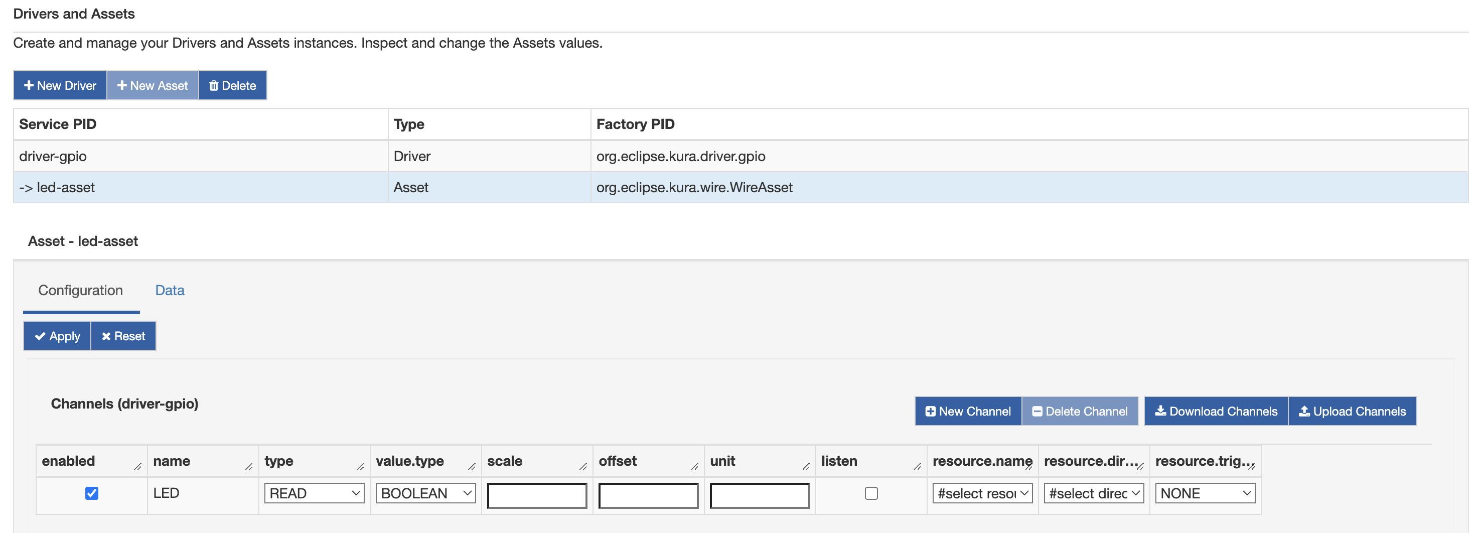
- Click "Apply".
-
As in point 3., create a new asset as shown below:
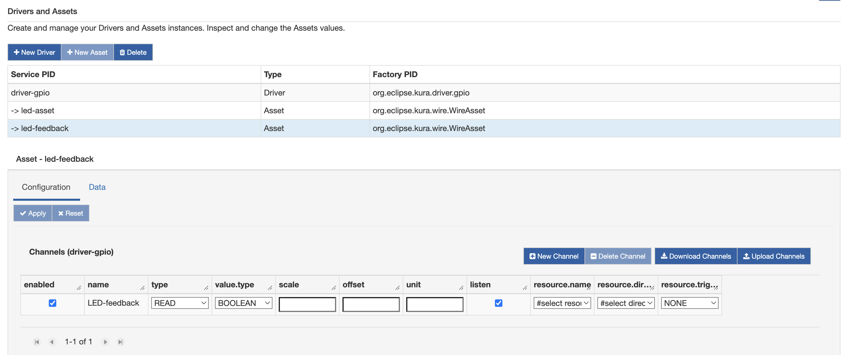
- Click "Apply".
-
Click on "Wires" under "System".
-
Add a new "Timer" component and configure the interval at which the LED will be toggled.
-
Add a new "Script Filter" (it can be downloaded from the Eclipse Marketplace and configure it with the following script:
-
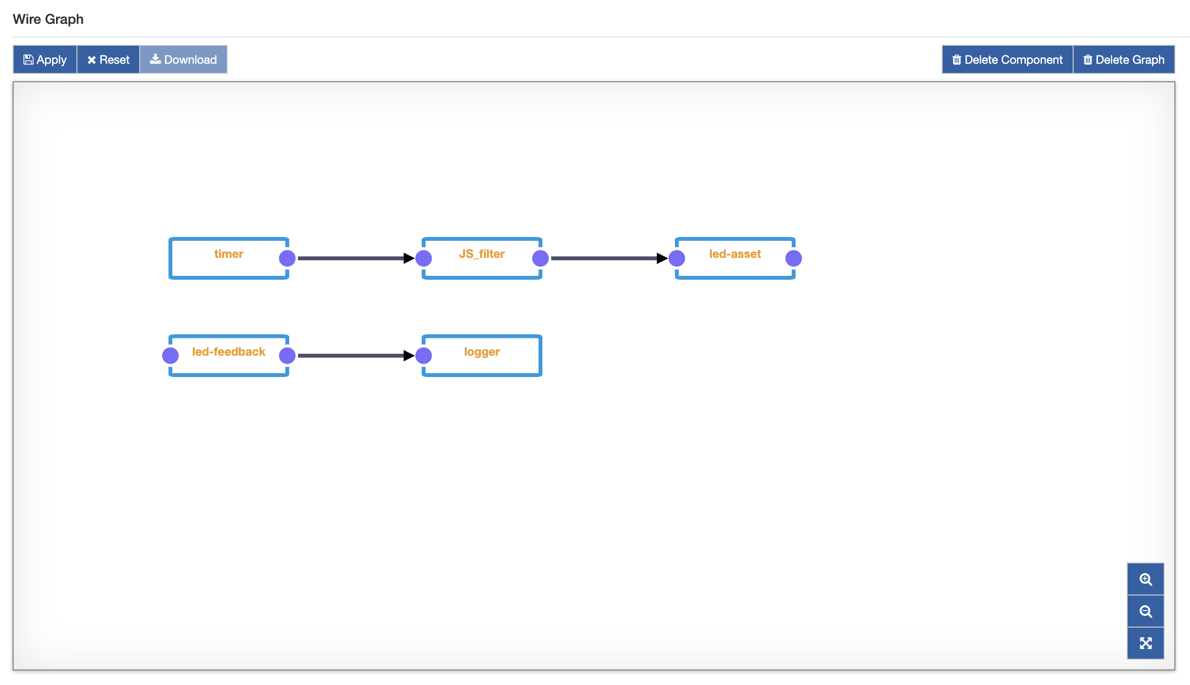
Add the "Asset" created at point 3 and connect the "Timer" to the "Filter" and the latter to the "Asset".
-
Add the "Asset" created at point 4.
-
Add "Logger" component and set log.verbosity to "VERBOSE".
-
Connect the latter "Asset" to the "Logger". The resulting Wire Graph should be as below:
-
Click on "Apply". After a while, the led on the breadboard should start to blink at a rate defined by the "Timer" as shown below:
Moreover, the kura.log file should show a long sequencce of messages reporting that the value from the input gpio is changed:
2018-04-09 13:08:42,990 [Thread-3289] INFO  o.e.k.i.w.l.Logger - Received WireEnvelope from org.eclipse.kura.wire.WireAsset-1523276074484-23
2018-04-09 13:08:42,991 [Thread-3289] INFO  o.e.k.i.w.l.Logger - Record List content:
2018-04-09 13:08:42,992 [Thread-3289] INFO  o.e.k.i.w.l.Logger -   Record content:
2018-04-09 13:08:42,993 [Thread-3289] INFO  o.e.k.i.w.l.Logger -     LED_Feedback : false
2018-04-09 13:08:42,993 [Thread-3289] INFO  o.e.k.i.w.l.Logger -     assetName : GPIOAssetFeedback
2018-04-09 13:08:42,994 [Thread-3289] INFO  o.e.k.i.w.l.Logger -     LED_Feedback_timestamp : 1523279322990
2018-04-09 13:08:42,994 [Thread-3289] INFO  o.e.k.i.w.l.Logger -
2018-04-09 13:08:44,988 [Thread-3291] INFO  o.e.k.i.w.l.Logger - Received WireEnvelope from org.eclipse.kura.wire.WireAsset-1523276074484-23
2018-04-09 13:08:44,989 [Thread-3291] INFO  o.e.k.i.w.l.Logger - Record List content:
2018-04-09 13:08:44,989 [Thread-3291] INFO  o.e.k.i.w.l.Logger -   Record content:
2018-04-09 13:08:44,989 [Thread-3291] INFO  o.e.k.i.w.l.Logger -     LED_Feedback : true
2018-04-09 13:08:44,989 [Thread-3291] INFO  o.e.k.i.w.l.Logger -     assetName : GPIOAssetFeedback
2018-04-09 13:08:44,989 [Thread-3291] INFO  o.e.k.i.w.l.Logger -     LED_Feedback_timestamp : 1523279324988